This report serves as a compact technical reference, a short-supply analysis, and a procurement action plan for US buyers. It summarizes key specs to confirm, tests and qualification data to request, how to read current supply signals, and pragmatic sourcing tactics to reduce schedule and cost risk for embedded designs using compact MEMS/crystal oscillators.
1 — Product overview & key specifications
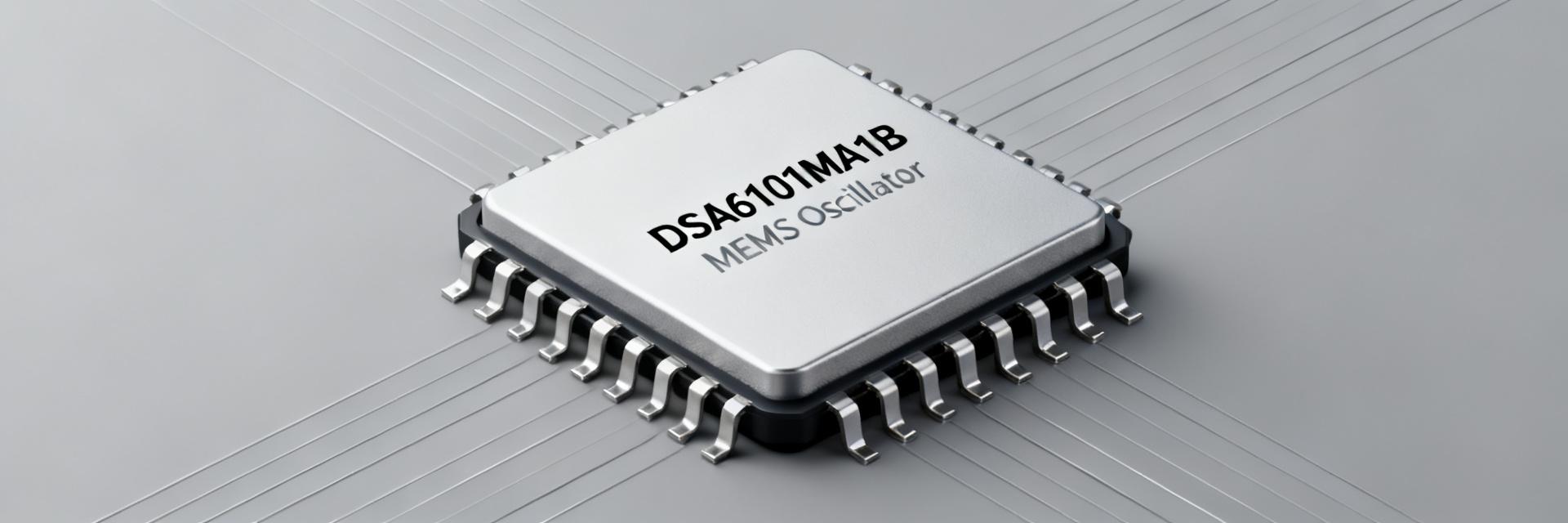
1.1 — What the DSA6101MA1B is
The part is a small form-factor MEMS/crystal-based oscillator family optimized for low-power embedded and RTC applications; commonly available frequencies include RTC staples (32.768 kHz) and small-signal clock rates in the kHz–MHz range. Typical supply voltages span 1.8 V to 3.3 V variants with an enable/disable control pin for low-power standby. This oscillator is intended for consumer electronics, industrial embedded systems, and automotive-grade use where temperature and reliability grades are specified by manufacturer documentation.
1.2 — Critical electrical and mechanical specs to highlight
- Frequency & stability: common choices include 32.768 kHz and 24–33.33 MHz class frequencies; stability thresholds to evaluate are initial accuracy (±10–±50 ppm) and temp stability (e.g., ±20 ppm over specified temperature range).
- Power and behaviour: supply voltage ranges typically 1.8 V–3.3 V; active current often in the low microamp to low milliamp range with standby currents in nanoamp to microamp; enable pin usually asserts high or low to gate output—confirm polarity and input thresholds.
- Package & environment: 4-pin VLGA/4-VFLGA style small packages, temperature grades spanning commercial to automotive, and moisture/reflow classifications for SMT assembly; ensure mechanical dimensions and pad footprint match PCB constraints.
| Parameter Type | Typical Range / Value | Supply Impact Metric |
|---|---|---|
| Available Frequencies | 32.768 kHz, 24.000 MHz, 33.333 MHz | High variation in lead time by variant |
| Supply Voltage | 1.8V to 3.3V options | Standard industrial profiles |
| Temperature Stability | ±10 ppm to ±50 ppm | Automotive-grade options are tighter |
| Package Style | 4-pin VLGA / VFLGA Footprints | SMD equipment compatible |
2 — Detailed data dive: performance metrics & test considerations
2.1 — Frequency accuracy, stability, ageing, and environmental performance
Key numbers to request are initial accuracy (ppm), temperature stability curve, and ageing (ppm/year). For example, a ±20 ppm stability implies a time drift of roughly 52 seconds per 30-day month (20×10⁻⁶ × 2,592,000 seconds ≈ 52 s) and about 631 seconds (~10.5 minutes) over a full year—important when building timing budgets for RTC sync or low-power wake intervals. Also check shock, vibration and ESD ratings to ensure field reliability in the intended mechanical environment.
2.2 — Test, qualification and reliability indicators
Ask suppliers for life-test hours, accelerated aging reports, temperature-humidity-bias (THB) data, and any AEC-like automotive screening if required. Request DHTOL-style test results and statistical pass/fail rates across lots; acceptance criteria should include ppm drift thresholds after burn-in, mechanical shock survival, and ESR/oscillation margin data so engineers can map component-level failure modes into system risk.
3 — Current supply landscape & market signals for DSA6101MA1B
3.1 — Inventory, lead-time patterns and pricing signals
Current supply checks show distributor stock can be fragmented by frequency and package; quoted lead times vary strongly with order quantity. Track “current supply” weekly using distributor listings and RFQs: small single-unit availability often shows inflated unit pricing, while larger pack quotes reveal extended lead times. Monitor MOQ effects and price breaks; if lead time for critical frequency exceeds twelve weeks, escalate procurement actions and consider staggered ordering.
3.2 — Risk indicators and variant-specific shortages
Legacy or uncommon frequencies and specialty temperature grades tend to be tighter than common RTC parts. Red flags include persistent out-of-stock status, rapid unit-price increases above 15–25%, and availability only in non-standard packaging. Mitigation thresholds: if lead time > 12 weeks or price delta > 20%, evaluate alternate frequencies, alternate suppliers, or a design swap rather than single-supplier dependence.
4 — How to evaluate and select the right DSA6101MA1B variant
4.1 — Decision checklist for engineers (technical selection criteria)
- Required frequency and tolerance (ppm)
- Operating temperature grade and vibration/shock specs
- Supply voltage and power budget (active/standby)
- Package footprint and board-side clearance
- Enable/disable polarity and startup behaviour
- Sourcing constraints: lead time, MOQ, and lifecycle status
4.2 — Design-in considerations and footprint notes
PCB layout tips: place a dedicated decoupling capacitor (0.1 µF) close to the device VCC pin, keep clock traces short and routed away from high-current nets, and observe recommended pad geometry to avoid soldering defects. Consider moisture sensitivity level and reflow profile guidance from manufacturer documentation. Red flags include mismatched voltage domains or leaving enable pin floating—document expected states and add pull-ups/pull-downs as required.
5 — Procurement playbook: sourcing tactics and mitigation checklist
5.1 — Short-term sourcing tactics
Immediate steps: buy available inventory for critical frequencies, request lot and age information, secure samples for qualification, and consider buy-to-build for imminent production runs. Ask suppliers for lead-time trend data and request staggered delivery to smooth cash and storage impact. Prioritize unit purchases that close immediate schedule gaps while avoiding excessive obsolescence exposure.
5.2 — Medium/long-term strategies (alternates & design resilience)
Long-term strategies include qualifying alternates by electrical equivalence rather than brand, multi-sourcing, planning last-time-buys when lifecycles loom, and designing pin-compatible oscillator footprints to permit swapping. For contract planning, hold safety stock of 3–6 months for critical parts and extend forecast horizons to 12–18 months depending on product life and production cadence.
Summary / Conclusion
- Confirm critical specs before selection: frequency, tolerance, temp grade, power, and package to prevent late redesigns; verify against manufacturer documentation and lab test data.
- DSA6101MA1B-024.0000TVAO supply posture is constrained for some variants—monitor lead time and price signals weekly and treat frequencies with extended lead times as at-risk in BOM reviews.
- Immediate procurement actions: secure small buys for qualification, request lot/age info, and stagger orders; consider buy-to-build for short-term continuity.
- Design choices to reduce risk: support alternate frequencies and pin-compatible footprints, set safety-stock targets, and incorporate multi-sourcing in contract forecasts.
FAQ
What frequencies and tolerances are available for DSA6101MA1B?
Available frequencies typically span RTC staples like 32.768 kHz and higher clock rates (e.g., 24–33.33 MHz); tolerances often range from ±10 ppm to ±50 ppm depending on variant. Confirm the exact frequency, stability over temperature, and ageing specs in manufacturer documentation before design lock.
How long are current lead times and how often do they change for DSA6101MA1B?
Lead times can range from a few weeks to multiple months and change rapidly; tracking distributor availability and RFQ responses on a weekly cadence is recommended. Escalate when quoted lead times exceed your risk threshold (commonly 12 weeks for critical items).
What test reports should I request before qualifying this oscillator?
Request life-test hours, accelerated ageing (ppm/year), temperature-humidity-bias results, shock/vibration survivability, ESD specs, and any automotive-like qualification data if required. These documents let procurement and engineering align acceptance criteria with system reliability goals.
What are the recommended PCB layout and design-in guidelines for the DSA6101MA1B?
Place a dedicated decoupling capacitor (0.1 µF) close to the device VCC pin, keep clock traces short and routed away from high-current nets, and observe recommended pad geometry to avoid soldering defects. Ensure that you document expected states for the enable pin and add pull-up or pull-down resistors as required instead of leaving it floating.