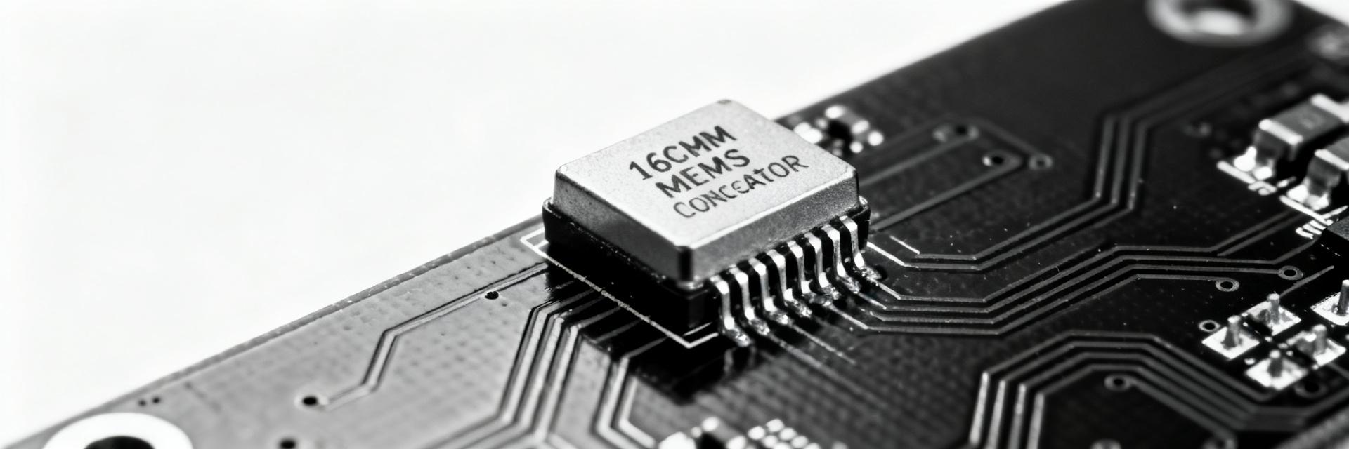
A typical MEMS oscillator in its class delivers stable frequency with low power and compact packaging; the representative parameters for this family—nominal frequency, stability, supply range, and operating temperature—drive selection risk in high-reliability systems. This article breaks down the core specs and provides a practical sourcing checklist to reduce procurement and integration surprises.
This piece delivers a precise spec breakdown, design/integration notes, and a practical sourcing checklist for the part. Reader outcome: Engineers and procurement specialists will be able to validate the device for their BOM, integrate it into PCB designs, and run a pre-production sourcing and test gate.
(1/5) — Product overview & application fit
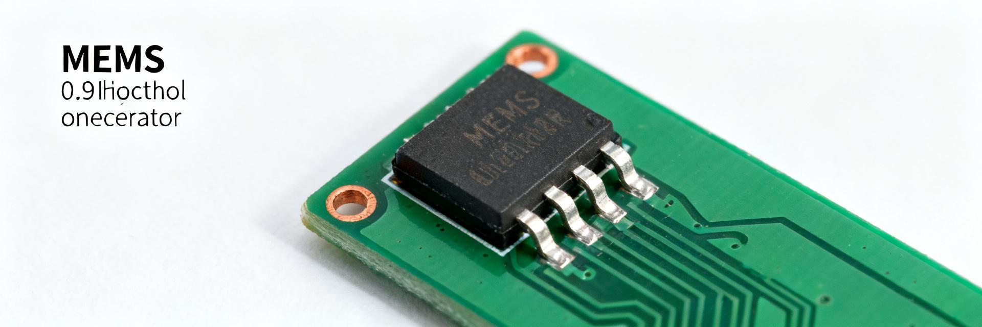
— Core identity & top-line specs
At a glance, identify the part by nominal frequency, stability, supply range, temp range, package, pins and output type. Datasheet fields are authoritative for each parameter. Use the short spec snapshot below when comparing candidates.
| Parameter | Typical Value / Range |
|---|---|
| Nominal frequency | 3.9 MHz |
| Frequency stability | ±20 ppm over specified temp |
| Supply voltage | 2.5–3.3 V |
| Operating temp | -40 to +85 °C |
| Package | 7.0 × 5.0 mm, 6 leads |
| Output type | LVCMOS / single-ended (confirm on datasheet) |
| Typical jitter/duty | Low ps-range jitter; ~50% duty (specify on datasheet) |
— Typical use cases & fit-for-purpose checklist
Determine fit by application domain—industrial clocks, communications timing, and consumer appliances each have distinct tolerance for stability and environmental stress. MEMS devices trade off size, ruggedness and supply flexibility vs. traditional crystal oscillators. Choose this part when board space, moderate stability (20 ppm) and -40/+85 °C range meet system requirements; favor crystals for ultra-high stability or tight phase-noise budgets.
- Ideal for embedded microcontroller clocks where 20 ppm is acceptable and small package is required.
- Good for consumer and some industrial network timing if output type and jitter meet link budgets.
- Avoid for high-end RF or precision timing where crystal oscillators or disciplined references are needed.
(2/5) — Deep specs breakdown & interpretation
— Electrical and timing parameters to validate
Key electrical/timing fields directly affect system behavior: frequency stability, phase noise/jitter, output compatibility, supply current and drive. Datasheet tables typically list worst-case and typical values across temp and supply limits. Confirm the worst-case stability across temp and aging; verify phase noise at offset frequencies relevant to your system; ensure output level and drive match receiver input and that supply noise sensitivity is characterized.
- Frequency stability: confirm total ppm including initial tolerance, temp, and aging—this defines long-term timing drift.
- Phase noise / jitter: use the specified rms jitter to check against system bit-error-rate and PLL capture budgets.
- Output compatibility: match LVCMOS/PECL levels and drive; check rise/fall times and duty cycle for digital timing.
- Supply current and sensitivity: plan decoupling and upstream regulator headroom to avoid frequency modulation under load.
— Mechanical, thermal, and reliability constraints
Package size, mounting, thermal limits and solder profile drive PCB layout and qualification. Datasheet mechanical drawings and recommended solder profiles offer actionable constraints. Keep thermal vias and copper pour considerations, respect orientation for optimal solder fillet, and run thermal cycling plus vibration tests if the part will see harsh environments.
- PCB keepout: maintain manufacturer-recommended clearance and place no large copper pours directly under the package unless thermally qualified.
- Mounting: align pin 1 orientation to footprint; confirm pad finish and solder mask openings match recommended footprint.
- Qualification: include temperature cycling, humidity soak, and vibration per product reliability needs.
(3/5) — Design & integration checklist
— Schematic and PCB integration steps
Integration rules mitigate signal integrity and reliability issues. Practical board-level experience shows termination, decoupling and return paths are common failure sources. Apply the following rules directly when placing and routing the oscillator.
- Place the oscillator close to the clock consumer to minimize trace length and stubs.
- Provide a dedicated solid ground plane with via stitching around the package.
- Use recommended decoupling: 0.1 µF close to Vcc pin and a 1 µF bulk cap nearby on plane.
- If differential/PECL output, terminate per datasheet (AC/DC termination) and route as differential pair with controlled impedance.
- Keep noisy power traces and switching regulators away from the oscillator; use ferrite beads if required.
- Verify footprint dimensions and solder mask per mechanical drawing before PCB fab.
— Test and validation plan before production
A concise test matrix catches integration and sourcing defects early. Typical production gates include frequency, jitter and environmental tests. Run these functional checks on incoming samples and first articles; set pass/fail thresholds from datasheet worst-case specs.
| Test | Method | Acceptable Range |
|---|---|---|
| Frequency at 25°C | Frequency counter, 1 min avg | Within ±specified nominal ppm |
| Jitter | Phase noise or TIE RMS measurement | Below specified rms jitter |
| Supply sensitivity | Vary Vcc ±5% | No frequency excursion beyond spec |
| Start-up time | Power cycle timing | Meets datasheet start-up max |
| Temp sweep | Chamber -40 to +85°C | Frequency within total stability budget |
(4/5) — Sourcing, procurement & lifecycle checklist
— Procurement checklist: what to request from suppliers
A robust RFQ reduces acceptance risk. Suppliers should supply traceability and compliance documents. Request the following items verbatim to enforce consistency across quotes and shipments.
- Complete datasheet and mechanical drawing.
- Lot traceability, date code, and manufacturing site statement.
- Packaging format (tube/reel), quantity per reel/tube.
- RoHS/REACH declarations and relevant certificates of conformance.
- Storage/shelf-life conditions and recommended handling.
- Sample availability and sample test reports.
- Counterfeit prevention and inspection records (if available).
- Lead time estimates, MOQ, and pricing tiers for 100, 1k, 10k units.
- Quality certifications or supplier quality plan summary.
- Cross-reference part numbers and approved alternates list.
— Risk controls: availability, lead time, authenticity & cost drivers
Watch for red flags like sudden lead-time jumps or marking changes. Procurement best practice uses authorized channels and incoming inspection. On receipt, verify packaging, date codes, and perform visual vs. datasheet marking checks plus electrical spot tests on a sampling basis; escalate discrepancies immediately.
- Receiving SOP: lot verification, visual marking check, sample functional test (frequency/jitter).
- Counterfeit indicators: inconsistent markings, unusual packaging, anomalous pricing.
- Mitigation: authorized suppliers, dual-source planning, demand forecasting and safety stock.
(5/5) — Cross-checks, alternates & real-world sourcing examples
— How to identify acceptable alternates and replacements
Alternates must be matched on critical electrical and mechanical dimensions. Differences in drive or startup translate to system-level issues. Prioritize frequency, stability, output type, pinout and temp range; then bin candidates into A/B/C tiers based on drop-in likelihood and required engineering effort.
- A-tier: Pin-compatible, same output type, equal or better stability and temp range.
- B-tier: Minor footprint or drive differences requiring small layout or termination changes.
- C-tier: Different output or supply—requires redesign or firmware adjustment.
— Example sourcing scenario & negotiation points
Urgent 1k-unit order requires tactical supplier engagement. Expedited supply often trades on price, packaging and MOQ. Execute these negotiation steps to secure expedited production while controlling cost and risk.
- Request sample ship and first-article test report immediately.
- Offer tiered pricing for confirmed lead-time commitments (expedited vs standard).
- Negotiate packaging (reel vs tube) to reduce handling time.
- Ask for partial shipments or consignment to meet short-term demand.
- Confirm traceability and agree acceptance tests on receipt.
- Establish fallback alternates and lead-time triggers for switch-over.
Summary / Conclusion
Recap: The DSA1222NI3-3M900000VAO fits applications needing a compact MEMS oscillator with moderate stability, low power and standard temp range; verify frequency stability, output compatibility and jitter first. Top sourcing actions: demand datasheet and lot traceability, perform incoming spot-tests, and plan dual-source options. Final recommendation: choose → validate → procure → test. Use the procurement checklist above as your RFQ template and pre-production gate.
Frequently Asked Questions
What are the key parameters to check in a DSA1222NI3-3M900000VAO datasheet?
Check nominal frequency (3.9 MHz), total frequency stability (±20 ppm including temp and aging), output type (LVCMOS), rms jitter, supply current, operating temperature range (-40 to +85 °C), package dimensions (7.0 × 5.0 mm), and recommended solder profile.
How should sourcing risk be mitigated for oscillators?
Mitigate risk by using authorized distributors, requesting lot traceability and certificates of conformance, performing incoming visual and electrical spot tests on samples, maintaining safety stock, and qualifying alternates before switching production supply.
What PCB practices ensure reliable oscillator performance?
Place the oscillator close to the load, provide a solid ground plane with stitched vias, use recommended decoupling (0.1 uF close to Vcc and 1 uF bulk cap nearby), follow precise termination guidelines, and avoid routing noisy power traces nearby.
How does a MEMS oscillator like DSA1222NI3-3M900000VAO compare to traditional crystal oscillators?
MEMS oscillators offer superior mechanical shock and vibration resistance, smaller form factors, and shorter lead times, though traditional quartz crystals may offer lower phase noise or tighter absolute frequency stability for specialized RF applications.