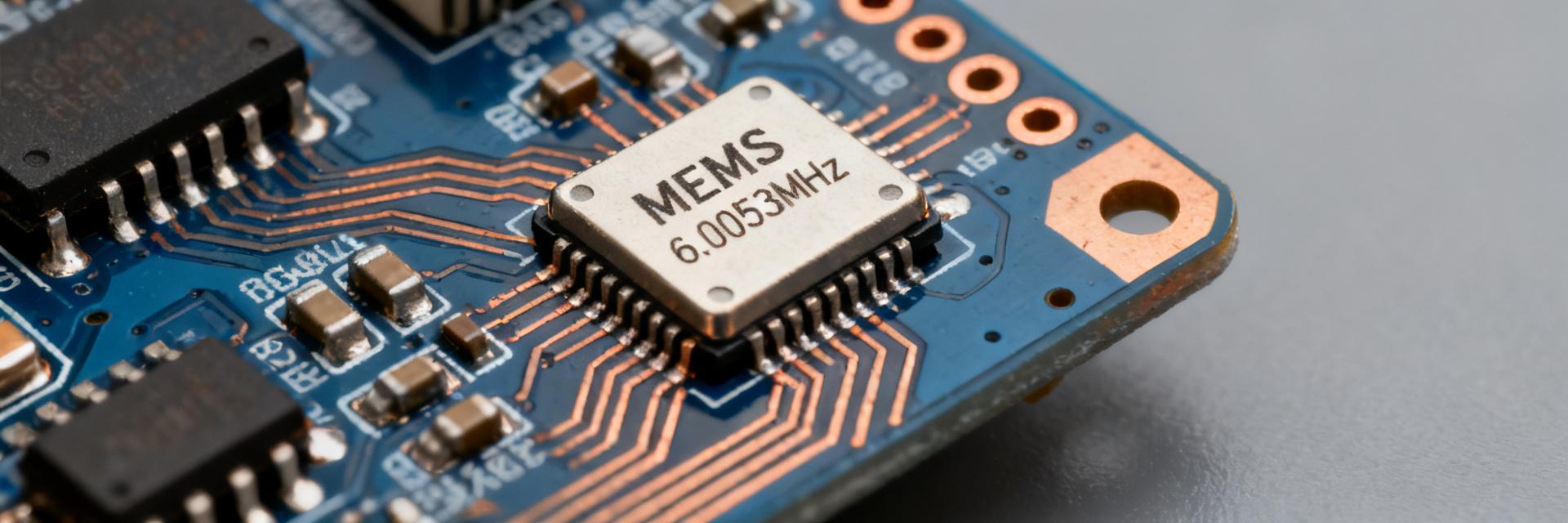
Point: Recent consensus estimates place the MEMS oscillator market in a sustained double‑digit CAGR range through the mid‑term, and 12MHz MEMS oscillator demand is measurable across IoT and automotive timing needs. Evidence: multiple market reports converge on mid‑teens CAGR ranges and growing OEM replacement of crystals. Explanation: that trend reflects miniaturization and robustness priorities in edge devices and automotive modules.
Point: This article focuses on technical specs buyers care about, US market drivers, and practical guidance for design and commercialization. Evidence: engineers and product managers prioritize low power, jitter, and qualification guidance when selecting timing sources. Explanation: practical spec thresholds and validation steps below translate market opportunity into implementable product and design choices.
Why 12MHz Matters in the MEMS Oscillator Landscape (Background)

Point: 12MHz is a frequent choice where modest frequency with low power and simple clock trees suffice. Evidence: typical low‑power microcontrollers, legacy serial interfaces, and many IoT radio front ends accept 8–16MHz reference clocks. Explanation: at 12MHz designers balance MCU wake timing, peripheral sampling, and RF PLL reference needs with minimal BOM impact.
Role of 12MHz in common applications
Point: 12MHz fits battery‑operated sensor nodes, small radios, and legacy interface timing. Evidence: deployment profiles show microcontrollers and narrowband radios needing sub‑100µs latency and single‑digit ppm timing for sleep/wake cycles. Explanation: designers select 12MHz for power efficiency and predictable wake timing rather than highest frequency performance.
- Sample profile: battery sensor node — 12MHz, <50µA active oscillator current.
How 12MHz compares vs other frequency points and crystal-based solutions
Point: MEMS at 12MHz trades slightly higher cost per unit for size, ruggedness, and integration over crystals. Evidence: MEMS parts remove fragile cut crystals and often provide wider temp ranges and shock tolerance. Explanation: decision criteria include size, power, frequency stability, and total cost over lifecycle—choose 12MHz MEMS when ruggedness and integration outweigh minimal unit cost savings.
- Quick pro/con: MEMS = rugged + integrated; crystal = lowest BOM in legacy high‑volume designs.
Market Size & Growth Forecast for 12MHz MEMS Oscillators (Data analysis)
Point: Consensus ranges indicate the broader MEMS oscillator market rising in mid‑teens CAGR, with 12MHz representing a steady, if not dominant, segment. Evidence: analyst summaries cite strong IoT node growth and automotive timing replacement as primary drivers. Explanation: 12MHz share depends on segment adoption—consumer IoT yields volume while automotive/industrial adoption yields higher ASPs and extended margins.
Current estimates and CAGR outlook (US-focused)
Point: US demand scenarios show near‑term growth from IoT rollouts and medium‑term uplift from automotive qualification cycles. Evidence: consensus forecasts present a base case (mid‑teens CAGR) and an accelerated case if automotive AEC‑like adoption broadens. Explanation: procurement timelines in US OEMs mean multi‑year qualification for automotive, but consumer/industrial transitions can scale volume sooner.
- Scenario snapshot: base case mid‑teens CAGR; upside tied to automotive module replacements.
Market drivers and constraints specific to 12MHz devices
Point: Drivers include miniaturization, reliability needs, and low‑power IoT growth; constraints center on incumbent crystal costs and supply chain volatility. Evidence: design teams prioritize extended temp and shock tolerance for in‑vehicle and industrial use, while consumer cost sensitivity favors lowest BOM. Explanation: suppliers must match reliability expectations and competitive pricing to expand 12MHz share.
- Key constraint: crystal price advantage in very high volume legacy BOMs.
Segment & Application Analysis: Where 12MHz Wins (Data + method)
Point: 12MHz wins where modest frequency meets tight power and form‑factor constraints. Evidence: consumer wearables and many IoT endpoints operate on strict power budgets and require small packages. Explanation: product profiles trade amplitude jitter for lower supply current and smaller footprint.
Consumer & IoT segment: volume, performance trade-offs
Point: In consumer IoT acceptance depends on low RMS jitter, low current, and competitive unit pricing. Evidence: example device — battery sensor node demands <100ps RMS jitter and <50µA active current to preserve runtime. Explanation: suppliers targeting consumer volume must optimize power and price while keeping oscillator specs adequate for radio and MCU timing.
- Example thresholds: RMS jitter <100ps, active current <50µA.
Automotive, industrial, and communications niches
Point: These niches demand extended temperature ranges, traceable qualification, and lifecycle support. Evidence: automotive modules require AEC‑like qualification, extended temp grades, and documented aging. Explanation: 12MHz adoption in these niches depends on supplier ability to provide qualification kits, long‑term reliability data, and controlled manufacturing processes.
- Typical demand: temp grade −40°C to +125°C, documented aging <5ppm/yr target.
Key Oscillator Specs Buyers Need: Practical Spec Guide for 12MHz
Point: Core oscillator specs map directly to system performance and must be evaluated early in selection. Evidence: frequency stability, phase noise, RMS jitter, supply current, and voltage range drive system margins. Explanation: translate spec numbers into application impact—for example, phase noise affects PLL lock time and radio adjacent‑channel performance.
| Specification Parameter | MEMS Oscillator Target (12MHz) | Quartz Crystal Solution |
|---|---|---|
| Frequency Stability | ±20 ppm to ±100 ppm | ±10 ppm to ±50 ppm |
| Active Current | <50 µA (Low-Power Core) | N/A (Passive, depends on MCU amplifier) |
| RMS Jitter | <100 ps (Typical) | <1 ps (Ultra-Low Jitter Advantage) |
| Shock & Vibration Resistance | High (>20,000 G rating) | Low/Moderate (Fragile physical quartz) |
| Form Factor Size | Ultra-small (1.6 x 1.2 mm or lower) | Larger (typically 2.0 x 1.6 mm minimum) |
Electrical specs: frequency stability, phase noise, jitter, supply current/voltage
Point: Define and target numeric bands appropriate for 12MHz applications. Evidence: practical thresholds include ±20–100ppm stability across temp for general IoT, RMS jitter <100ps for many radios, phase noise consistent with PLL lock requirements. Explanation: choose tighter stability or lower jitter where RF or precision sampling demand it, accepting higher power if necessary.
- Target bands: stability ±20–100ppm; RMS jitter <100ps; supply 1.8–3.3V.
Mechanical & environmental specs: packaging, temperature, aging, reliability indicators
Point: Packaging and environmental specs determine suitability for automotive/industrial use. Evidence: recommended selections include ceramic or molded packages with robust solder fillets and proven moisture resistance. Explanation: require documented aging rates, shock/vibration data, and available automotive temp grades when specifying for long‑lifetime products.
- Recommended: package options (SMD small package); aging <5ppm/yr for long life.
Integration Checklist & Validation Steps for Designers
Point: Early layout and validation reduce integration risk and preserve timing integrity. Evidence: PCB layout, decoupling, and power sequencing strongly affect jitter and EMI. Explanation: follow tight decoupling and separation rules, then validate with temperature and supply stress tests to confirm in‑system behavior.
PCB layout, power sequencing and decoupling best practices for 12MHz MEMS oscillators
Point: Minimize noise coupling and optimize supply stability. Evidence: practical rules are short power traces, local 0.1µF and 1µF decoupling, star ground to oscillator return, and keep clock trace short and terminated. Explanation: these steps reduce supply‑induced jitter and radiated emissions that degrade system timing.
- Layout tips: 0.1µF+1µF decoupling, short clock trace <10mm when possible.
Test, qualification and validation plan (bench and field)
Point: Define lab and field tests with clear pass/fail thresholds. Evidence: essential tests include frequency vs temperature, phase noise, jitter, and accelerated aging/burn‑in. Explanation: combine bench characterization with targeted field trials under supply variation and vibration to surface real‑world issues early.
- Essentials: temp sweep, phase noise, 1000‑hour burn‑in sample test.
Commercial & Product Strategy: How Suppliers and OEMs Win with 12MHz
Point: Differentiation and roadmap alignment convert technical advantage into market share. Evidence: suppliers offering low‑power, extended temp, and qualification support find faster OEM engagement in US markets. Explanation: combine product differentiation with accessible qualification kits and predictable pricing models to accelerate adoption.
Differentiation and channel strategy for suppliers
Point: Focus on value‑added services and targeted OEM outreach. Evidence: effective strategies include offering evaluation kits, application notes, and packaged qualification data for automotive/industrial. Explanation: these reduce OEM validation time and justify premium pricing for extended‑grade parts.
- Channel actions: evaluation kits + qualification packages for OEMs.
Product roadmap priorities for OEMs and system integrators
Point: Prioritize improved jitter, smaller packages, and qualification support. Evidence: roadmap items that matter are custom frequency options, lower power modes, and documented lifecycle support. Explanation: align roadmap timelines with typical US OEM procurement and multi‑year qualification cycles to capture design wins.
- Roadmap focus: smaller packages, lower jitter, qualification data.
Summary
- 12MHz MEMS oscillator demand aligns with MEMS oscillator market growth driven by IoT and automotive transitions; suppliers should target ruggedness and qualification to capture higher‑value segments and consumer volume simultaneously.
- Key oscillator specs—frequency stability, RMS jitter, phase noise, and supply current—determine suitability; practical thresholds (±20–100ppm, <100ps jitter) guide selection for most 12MHz use cases.
- Design and commercialization success requires early PCB/layout practices, focused validation (temp sweep, burn‑in), and supplier OEM support through evaluation kits and documented reliability.
Frequently Asked Questions
How does a 12MHz MEMS oscillator compare to a crystal for IoT?
MEMS offers better shock resistance, smaller form factors, and often wider temperature ranges than crystals, while crystals typically retain cost advantage in legacy high‑volume BOMs. For IoT, choose 12MHz MEMS when ruggedness, integration, and faster qualification matter more than minimal unit cost.
What oscillator specs should I prioritize for a low‑power 12MHz design?
Prioritize supply current and RMS jitter for low‑power designs: aim for active current <50µA and RMS jitter <100ps where radio performance is relevant. Frequency stability bands (±20–100ppm) are a secondary pick depending on PLL and RTC accuracy needs.
What qualification steps are essential for automotive use of a 12MHz MEMS oscillator?
Essential steps include selecting extended temp grade parts, obtaining documented aging and shock/vibration data, performing temperature cycling and long‑term burn‑in, and providing qualification kits to OEM labs. Align timelines to multi‑year automotive procurement cycles for successful adoption.
What is the projected market growth (CAGR) for MEMS oscillators in IoT and automotive?
Recent consensus estimates place the MEMS oscillator market in a sustained double-digit CAGR range through the mid-term, specifically in the mid-teens CAGR range. This growth is driven by expanding IoT node deployments and the systematic replacement of traditional quartz crystals in rugged automotive modules.