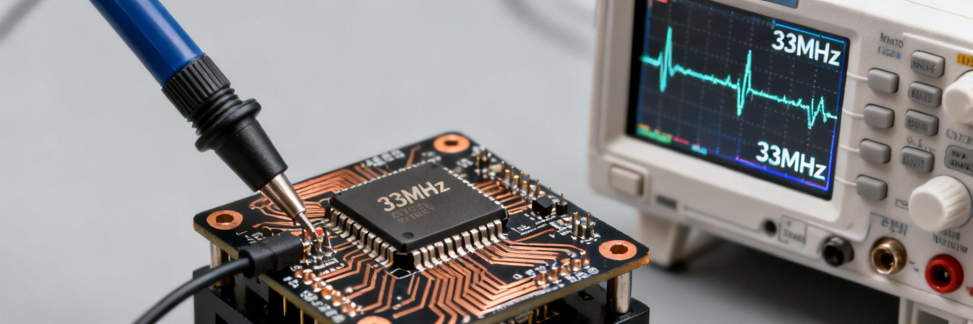
Struggling with jitter, footprint issues, or unreliable starts when integrating a 25MHz XO? This guide walks through the DSA1121BA3 pinout, full electrical specs, and practical PCB layout and routing tips so the clock comes up cleanly and stays stable on the board.
Background & Key Features
What the DSA1121BA3 is and where it's used
The DSA1121BA3 is a high-performance packaged SMD XO providing a fixed 25.000 MHz CMOS output. Typical applications include network PHYs, microcontrollers, and communication modules where a stable clock is required. Its low jitter and compact MEMS architecture make it suitable for constrained boards, though proper moisture handling is essential.
Quick Spec Snapshot
| Parameter | Typical / Notes |
|---|---|
| Nominal Frequency | 25.000 MHz |
| Frequency Tolerance | ±10–50 ppm |
| Startup Time | ≤10 ms |
| Output Type | CMOS / HCMOS |
| Supply Voltage | 1.8V / 2.5V / 3.3V |
| Output Drive | 8–16 mA typical |
| Current Consumption | 1–10 mA active |
| Duty Cycle | 50% ±5% |
| Phase Jitter | Sub-ps RMS (integrated) |
| Temp Range | -40°C to +85°C |
Complete Pinout & Electrical Characteristics
Pin-by-Pin Description
Mapping pins correctly is vital for assembly. For the DSA1121BA3: Pin 1 is Standby (logic high for active), Pin 2 is Ground, Pin 3 is the 25MHz Clock Output, and Pin 4 is VCC. Always confirm the enable polarity in your specific sub-variant to avoid inadvertent shutdowns.
PCB Footprint & Recommended Land Pattern
Recommended Footprint and Soldermask Rules
Typical SMD XOs use rectangular pads (approx 0.6mm x 0.9mm). Use a 1:1 soldermask opening or slightly non-soldermask defined (NSMD) pads for better solder wetting. Ensure a clear Pin 1 silkscreen indicator to prevent 180-degree rotation errors during SMT assembly.
Assembly and Reflow Guidance
Follow JEDEC MSL guidelines. Use a standard lead-free reflow profile with a peak temperature of 260°C for no more than 30 seconds. Avoid multiple reflow cycles if possible to maintain frequency stability and long-term reliability.
PCB Layout: Routing, Grounding & EMI Control
Power Decoupling & Ground Strategy
Place a 0.1 μF ceramic capacitor within 1–2 mm of the VCC pad (Pin 4). Use a dedicated ground via to a solid internal plane directly adjacent to Pin 2. This minimizes the return-loop inductance, which is critical for reducing phase jitter.
Output Routing and EMI Mitigation
- Keep clock traces shorter than 25mm to minimize antenna effects.
- Insert a 10–47 Ω series resistor close to Pin 3 to match impedance and damp overshoot.
- Route the clock signal over an uninterrupted ground plane; avoid crossing splits in the plane.
Summary Checklist
- Verify DSA1121BA3-025.0000TVAO pinout against the specific datasheet version.
- Ensure decoupling caps (0.1μF) are as close to the VCC pin as physically possible.
- Use series termination (22Ω typical) to maintain signal integrity on the 25MHz line.
- Validate startup and jitter levels across temperature extremes during bench testing.
FAQ
How should the DSA1121BA3 25MHz XO be decoupled on PCB?
Use a close-proximity 0.1 μF ceramic capacitor within 1–2 mm of the VCC pad, optionally backed by a 1 μF or 10 nF for low-frequency noise. Close placement lowers parasitic inductance, ensuring stable startup and lower phase noise.
What termination is recommended when routing a 25MHz XO clock?
A small series resistor of 10–47 Ω placed at the XO output is usually sufficient to damp reflections for short to moderate runs. This trades a slight decrease in slew rate for significantly cleaner edges and reduced EMI.
What test steps catch early integration issues with DSA1121BA3?
Verify rail voltage, decoupling, and orientation first. Then use a high-bandwidth scope with a short ground spring to measure amplitude, duty cycle, and jitter. Check frequency accuracy against the ppm spec using a frequency counter.
How to handle MSL and reflow for DSA1121BA3?
Treat as an MSL 1 or 3 device depending on packaging. Follow the vendor-specified reflow profile, ensuring ramp rates do not exceed 3°C/sec to prevent internal stress on the MEMS resonator structure.