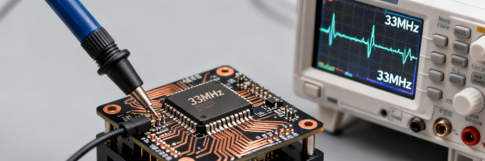
Point: Aggregate catalog and independent summaries often report very large nominal lifetimes for low-frequency MEMS timing devices. Evidence: Datasheet-extrapolated FIT-to-MTBF claims and limited accelerated-test reports can imply MTBFs in the 105–106 year equivalent range for 32.768 kHz parts. Explanation: such figures are statistical extrapolations, not literal service lifetimes, and require careful reconciliation with application stressors and field returns.
Point: This report gives three practical takeaways. Evidence: It clarifies realistic reliability expectations for a 32.768 kHz MEMS oscillator, explains how MTBF is measured and interpreted, and provides a specification/verification checklist for product development. Explanation: engineers and procurement teams will get the actions needed to convert vendor claims into verifiable reliability confidence.
Background: What a 32.768 kHz MEMS oscillator is and why reliability matters
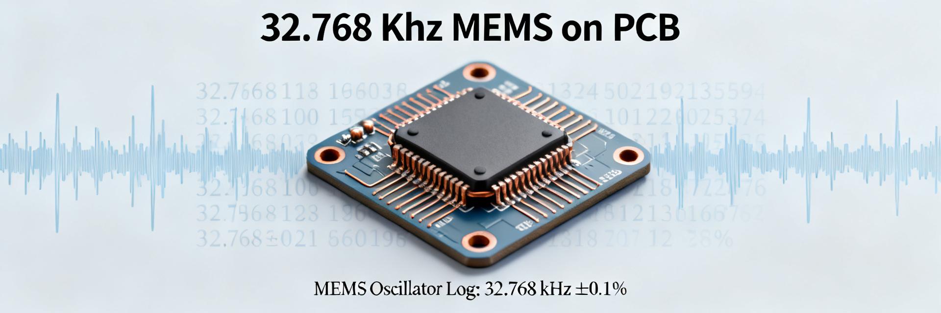
How the 32.768 kHz MEMS oscillator differs from quartz
Point: MEMS resonator + oscillator IC vs quartz crystal + amplifier yields different failure profiles. Evidence: MEMS devices integrate a micromachined resonator and drive/readout circuitry in a single package, while quartz relies on a discrete crystal element. Explanation: integration reduces board area and improves shock tolerance, but adds IC‑level failure modes (e.g., CMOS aging) that affect long‑term behavior in RTC and low‑power wearable use cases.
Key reliability-related specs to watch
Point: A short list of datasheet fields predicts field robustness. Evidence: extract MTBF/FIT, frequency stability (ppm over temp and time), supply current, shock/vibration ratings, humidity or ingress protection, and operating temperature range. Explanation: recording these values consistently across vendors enables apples‑to‑apples qualification and highlights tradeoffs between power, stability, and mechanical tolerance.
| Spec | Typical MEMS | Typical Quartz |
|---|---|---|
| Frequency stability | ±20–100 ppm | ±5–50 ppm |
| Supply current | 200 nA–1 µA | 100 nA–1 µA |
| Package size | 2–3 mm SMD | 2–7 mm crystal |
Hard numbers: MTBF, field data and statistical interpretations
MTBF definitions, calculation methods, and common pitfalls
Point: MTBF is a statistical metric, not a guaranteed lifetime. Evidence: vendors typically derive MTBF from accelerated stress tests, FIT calculations, or historical failure models, and sometimes conflate MTTF, useful life, and MTBF. Explanation: engineers must request test methods, acceleration factors, and confidence intervals—otherwise quoted MTBFs can be misleading for design decisions.
Summary of reported MTBFs and field study findings
Point: Reported MTBFs vary widely by method and conditions. Evidence: literature and datasheet‑derived ranges span roughly 104–106 years equivalent MTBF, depending on extrapolation and sample size. Explanation: the high end reflects aggressive statistical extrapolation from small failure counts; field returns and service data often imply much shorter useful lifetimes under real environmental stress.
| Source Type | Reported MTBF (equiv.) | Notes |
|---|---|---|
| HTOL extrapolation | 105–106 yr | small failure counts, high AF |
| Field returns | 103–105 yr equiv. | environment dependent |
Failure mechanisms and reliability drivers for 32.768 kHz MEMS oscillators
Common failure modes and root causes
Point: MEMS and associated ICs present distinct root causes. Evidence: failure mechanisms include packaging moisture ingress, stiction or contamination of the resonator, fatigue from mechanical stress, CMOS aging, and solder/joint failures. Explanation: prioritize mitigation based on application—battery‑powered consumer devices care more about low‑power drift; industrial units must prioritize mechanical and humidity robustness.
Environmental and usage factors that accelerate wear
Point: Temperature, humidity, and mechanical abuse dominate accelerated wear. Evidence: temperature cycling increases solder and package stress; high humidity enables corrosion or moisture-related shifts; continuous duty and frequent power cycling stress oscillator drive circuits. Explanation: apply conservative derating (narrower temp ranges, humidity-sealed packaging) and map accelerated test equivalents to expected field profiles.
Testing and qualification: practical methods to verify reliability
Recommended accelerated and stress tests
Point: A compact test suite exposes likely failures before production. Evidence: include HTOL (life stress), temperature cycling, humidity soak, mechanical shock/vibration, ESD, and power‑cycle endurance. Explanation: define pass/fail as frequency shift beyond spec (e.g., >±100 ppm for RTC use) or functional failure; document sample sizes and run durations to support statistical claims.
Data capture, statistical analysis, and reporting best practices
Point: Measurement discipline enables defensible MTBF projections. Evidence: log frequency vs time with timestamped measurements, apply Weibull or Arrhenius models for life projection, and report MTBF with confidence intervals. Explanation: recommend minimum sample sizes per test (e.g., 77–100 units for basic HTOL) and present both accelerated results and any available field return data to stakeholders.
Design and procurement playbook: specifying and assuring long-term reliability
Specification checklist for engineers and procurement
Point: Use a concise spec sheet to drive vendors. Evidence: require explicit frequency stability over temp, max supply current, package sealing/humidity rating, shock/vibration specs, HTOL test details including AF and sample size, warranty/return terms, and failure reporting. Explanation: include contract language requesting raw test logs, confidence intervals, and field return summaries as part of qualification.
- Require frequency stability (ppm) over specified temp range and aging limits.
- Specify shock/vibration and humidity ingress levels and supply‑current targets.
- Request HTOL details: temp, duration, sample size, acceleration factors, and failure definitions.
In-field monitoring, lifecycle planning and end-of-life criteria
Point: Field telemetry and lifecycle rules close the reliability loop. Evidence: monitor frequency drift, RTC sync errors, and power/failure events; maintain replacement thresholds and firmware fallbacks. Explanation: incorporate observed field MTBF into spare-part forecasts and trigger planned part replacement when drift or failure trends exceed conservative thresholds.
Summary / Conclusion
Point: Reconciling vendor MTBF claims with application reality is essential. Evidence: 32.768 kHz MEMS oscillator test extrapolations can imply very large MTBFs, but real-world stressors and small test sample sizes reduce practical confidence. Explanation: use the recommended test suite, spec checklist, and monitoring guidance to translate vendor claims into engineering assurance for product lifetime planning.
Key summary
- Realistic expectations: a 32.768 kHz MEMS oscillator can show very high extrapolated MTBF, but those figures depend on test method and sample size—verify with raw HTOL and field data.
- Critical specs: track MTBF/FIT methodology, frequency stability, shock/vibration, humidity rating, and operating temperature when qualifying parts.
- Qualification actions: run HTOL, temperature cycling, humidity soak, mechanical stress, and power‑cycle tests; log frequency vs time and report statistical intervals.
Frequently Asked Questions
How should MTBF for a 32.768 kHz MEMS oscillator be interpreted?
MTBF is a statistical metric estimating mean time between failures under a stated stress profile and confidence level. It is not a guaranteed calendar life. Engineers must review the test method, acceleration factors, and sample size behind any MTBF claim to assess applicability to their expected field environment.
Can MEMS replace quartz for long-term RTC reliability?
Yes, in many low‑power applications MEMS offers comparable or better mechanical robustness and comparable power consumption. However, long‑term frequency stability, aging behavior, and IC‑level failure modes differ; qualification must target the specific use case and environmental stresses.
What minimum tests should procurement demand to accept vendor MTBF claims?
Require HTOL with clear acceleration factors and sample sizes, temperature cycling, humidity soak, mechanical shock/vibration, and power‑cycle endurance. Demand raw logs, confidence intervals for MTBF, and any available field return data to validate vendor extrapolations.
What environmental factors most heavily accelerate MEMS oscillator aging?
Temperature extremes, high humidity, and severe mechanical environments dominate accelerated wear. Thermal cycling degrades package interfaces, while prolonged moisture exposure risks package ingress, and continuous duty cycles accelerate electrical wear of the drive CMOS ASIC.