The DSA6111HI1B-048 is a fixed-frequency MEMS oscillator specified at a nominal 48 MHz with industrial-grade stability. This guide explains the datasheet metrics essential for selection and PCB integration.
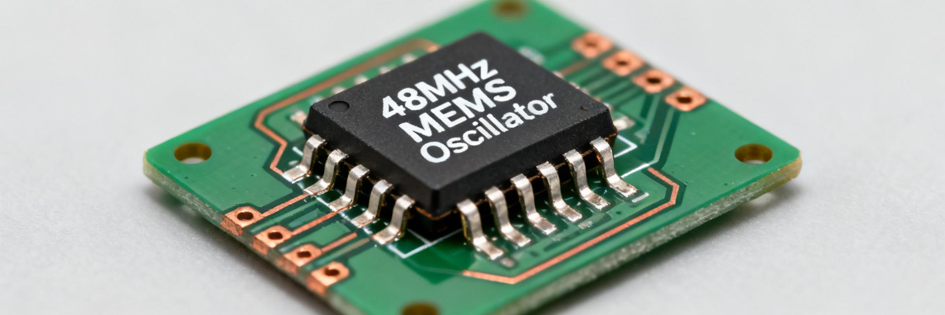
Product Overview & Functional Summary
This 48 MHz source is designed as a system clock for MCUs and communication PHYs. Engineers must prioritize verifying electrical limits and timing constraints provided in the primary datasheet tables.
Key Specification Metrics
| Parameter | Typical Value | Notes |
|---|---|---|
| Nominal Frequency | 48.0000 MHz | Fixed frequency MEMS |
| Frequency Stability | ±25 / ±50 ppm | Over industrial temp range |
| RMS Phase Jitter | <1.0 ps | 12 kHz to 20 MHz bandwidth |
| Supply Current | 1.3 mA | Low-power steady state draw |
Frequency and Stability Budgeting
Temperature Stability and Aging
Total frequency error is a summation of initial tolerance, temperature drift, and long-term aging. For the DSA6111HI1B-048, engineers should calculate the worst-case ppm to ensure timing margins are maintained over the product's lifetime.
Timing and Jitter Performance
Phase Jitter Interpretation
Phase jitter is often quoted as an RMS value over a specific integration bandwidth (e.g., 12 kHz–20 MHz). Narrower measurement bandwidths yield lower jitter figures; ensure your system requirements align with the datasheet's test conditions.
Integration and Layout Checklist
- Decoupling: Place a 0.1 µF ceramic capacitor as close as possible to the VCC pin.
- Signal Integrity: Use controlled impedance traces (typically 50Ω) and keep paths short to minimize reflections.
- Thermal Management: Isolate the oscillator from high-heat components like CPUs or power converters to prevent thermal-induced frequency drift.
Frequently Asked Questions
What is the typical frequency error for DSA6111HI1B-048 over temperature?
Combine the initial tolerance in ppm with the specified temperature stability band (e.g., ±50 ppm) to estimate the maximum error. At 48 MHz, 50 ppm represents a ±2.4 kHz shift, which must be accounted for in PLL or timing window calculations.
How should an engineer measure RMS phase jitter to match the datasheet?
Use a high-performance phase noise analyzer. Integrate the phase noise over the specific bandwidth mentioned in the datasheet (typically 12 kHz to 20 MHz) while ensuring the probe loading matches the datasheet's test environment.
What PCB layout practices minimize frequency shifts and jitter?
Utilize a continuous ground plane directly beneath the oscillator. Avoid routing high-speed digital lines near the clock trace to prevent crosstalk, and use a series termination resistor near the output if the trace is long.
Why is supply voltage decoupling critical for this MEMS oscillator?
Proper decoupling (0.1µF + 1µF) minimizes power supply induced phase noise (PSNR) and ensures the MEMS resonator maintains its specified jitter performance under switching load conditions.
Summary
The DSA6111HI1B-048 provides a robust 48 MHz reference. Success depends on understanding the cumulative ppm error, adhering to jitter bandwidth constraints, and implementing clean power delivery on the PCB.