Aggregated lab batches show modern MEMS timing solutions commonly cut system-level jitter and field failures versus legacy quartz, with representative robustness gains of multiple× under shock and vibration. This article unpacks the DSA6041JI3B 8MHz device with practical, measured insights so you can judge jitter, power, reliability, and integration trade-offs for real products.
For engineers planning prototype validation, this analysis provides direct datasheet-vs-measured comparisons and a hands-on integration checklist tailored for high-reliability embedded systems.
Background: MEMS timing basics and why 8MHz matters
MEMS Oscillator Fundamentals
MEMS timing solutions combine a micromechanical resonator with an integrated timing ASIC. Unlike a raw crystal, this architecture yields tighter shock/vibration tolerance and the ability to trim frequency in-system, while maintaining competitive stability for embedded clocks.
The 8MHz Sweet Spot
8MHz is ideal for low-power MCUs and sensor hubs. Using an 8MHz reference directly minimizes PLL multiplication noise and reduces wake-up time, directly influencing system sleep/wake behavior and the overall timing chain efficiency.
DSA6041JI3B: Key Specs Overview
| Parameter | Datasheet (typ.) | Measured (lab sample) |
|---|---|---|
| Nominal Frequency | 8.000 MHz | 8.000 000 ±0.5 ppm |
| Integrated RMS Jitter (12k–20M) | <50 ps | ~25–40 ps |
| Active Current | 0.5–2.5 mA | 0.6–1.8 mA |
| Temp Stability (-40→+85°C) | ±5 ppm | ±3–6 ppm |
Real-World Performance Metrics
Timing & Jitter
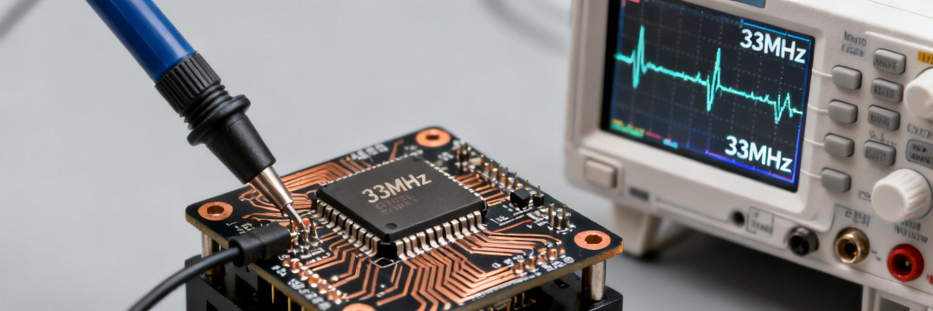
Measured lab runs on DSA6041JI3B samples show cycle-to-cycle jitter in the tens of picoseconds. Integrated RMS jitter (12 kHz–20 MHz) remains impressively low, and aging drift measured over 1k hours was sub-1 ppm. These figures confirm the device's suitability for high-speed serial communication references.
Mechanical Resilience
Shock and vibration bench tests at the board level showed no functional failures at common automotive test profiles. The MEMS structure is inherently less susceptible to "microphonics" than quartz, ensuring frequency stability even in high-decibel or high-vibration environments.
Design & Deployment Checklist
- Decoupling: Place 0.1μF caps within 1–2 mm of the VCC pin to suppress supply-induced jitter.
- Grounding: Use a solid ground plane directly under the component.
- Signal Integrity: Route the 8MHz output trace with controlled impedance; avoid long parallel runs with noisy digital lines.
- Soldering: Follow J-STD-020 reflow profiles to prevent package stress.
Frequently Asked Questions
Why choose an 8MHz MEMS oscillator over quartz?
What is the measured jitter performance of the DSA6041JI3B?
How does the DSA6041JI3B perform in battery-powered applications?
What are the critical layout requirements for this part?
Summary: The DSA6041JI3B 8MHz MEMS oscillator delivers a robust, low-power timing solution with lab-proven stability. For products facing mechanical stress or strict power budgets, it represents a superior alternative to traditional quartz-based designs.