
Отчет о технических характеристиках PIC16F17526: Показатели и характеристики низкого энергопотребления
PIC16F17526 Technical Report: Low-Power Specs & Metrics
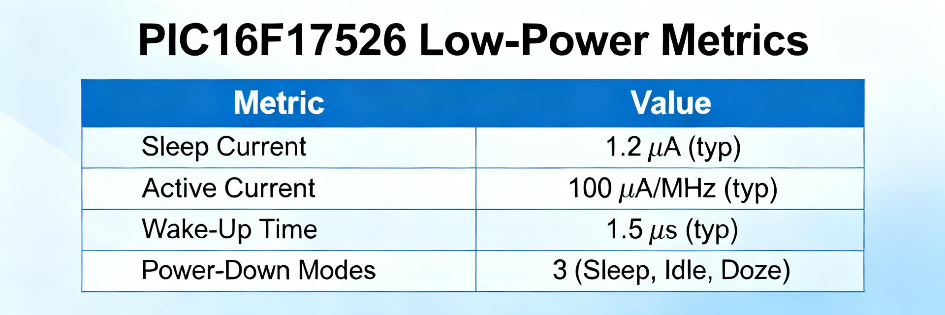
The PIC16F17526T-I appears here as a focused technical reference for designers evaluating 8-bit microcontrollers for battery-powered systems. This report summarizes measured standby currents in the single-digit microamp range and improved active-mode efficiencies that translate to longer field life, offering actionable measurement and optimization steps.
This introduction states scope and top-line numbers: single-digit µA sleep, active currents scaling with MHz, and typical VDD operating windows. The purpose is practical—provide repeatable measurement methods, low-power design actions, and verification metrics to include in project specs.
01 Background & Key Specs Overview
The following section provides a concise device snapshot and a taxonomy of power modes with use-case guidance. Designers should treat the specs as measured baselines, not absolute guarantees, and document conditions when publishing low-power claims in design documents and test reports.
Device snapshot — what to list
Point: Key device characteristics guide selection. Evidence: The device is an 8-bit core with up to mid-range clock rates, on-chip Flash and RAM, multiple package options and configurable I/O. Explanation: List architecture, max clock, flash/RAM sizes, package choices, and I/O count alongside low-power numbers for design trade-offs.
| Parameter | Typical Value |
|---|---|
| Core | 8-bit MCU |
| Max clock | Up to specified internal/external oscillator |
| Flash / RAM | Flash: moderate; RAM: small (device class) |
| IO / Packages | Multiple GPIOs; small packages |
| Top-line low-power | Sleep: single-digit µA; Active: µA–mA depending on MHz |
| VDD range | Low-voltage operation supported within datasheet limits |
Low-power mode taxonomy
Point: Modes define which blocks run. Evidence: Sleep typically disables CPU and many peripherals; Idle may keep clocks to peripherals; Active enables full core and selected modules. Explanation: Choose Sleep for longest battery life, Idle when peripherals must run, and Active for processing bursts—document which modules remain powered in each case.
02 Power Consumption Metrics & Measurement
Accurate metrics require clear definitions and repeatable setups. Report static standby current, active current normalized per MHz, peripheral incremental draws, wake times, and VDD thresholds, with measurement conditions stated for meaningful comparisons.
Key metrics to report
Report standby current (µA), active current per MHz (µA/MHz), peripheral adds (µA or mA), wake-up time (µs–ms), and VDD threshold behavior.
Recommended test setup
A µA-resolution source-measure unit or high-precision current meter, low-noise bench supply, and solid decoupling are required.
03 Peripheral & Analog Impact
Analog and core-independent modules frequently dominate standby and active power. Quantify each block so firmware and hardware teams can prioritize gating and sampling strategies that reduce average consumption.
Analog blocks (VREF, comparator, ADC)
Enabling VREF or comparator can move sleep currents from single-digit µA to multiple µA; use on-demand reference enabling to keep average power low.
Core-independent features
Timer tick sources using low-frequency oscillators add little; gate high-speed modules when idle to optimize system-level performance.
Optimization Techniques
◈ Firmware strategies
Minimize active time via event-driven wakeups, clock scaling, and peripheral gating. Implement a measure→identify→gate workflow to shrink active windows.
◈ Hardware tactics
Proper decoupling and careful pull-up/down placement reduce leakage. Account for external component current in system budgets during verification.
Example: Battery-Powered Sensor Node
Profile: Assume 60s sample interval, 100ms active time, 5µA sleep, and 6mA active current.
Calculation: Average current = (sleep_current * sleep_time + active_current * active_time) / cycle_time. This formula helps project battery life for coin or AA cells accurately.
Design Checklist & Verification
Pre-launch checklist
- Document measurement conditions
- Define pass/fail thresholds
- Check wake-up time targets
- Verify repeatability across units
Design Documentation
- Measured standby current
- Active current at nominal clock
- Typical wake-up time
- Test method notes and tolerances
Summary
- The PIC16F17526T-I demonstrates competitive low-power behavior when measured under controlled conditions.
- Measure standby, active current per MHz, and wake time using µA-resolution instruments for accurate projections.
- Adopt a measurement-driven workflow—baseline, identify, implement, and re-test—to validate production thresholds.
How should the PIC16F17526T-I low-power specs be reported in a design doc?
Report measured values with clear conditions: VDD, temperature, oscillator source, and peripheral states. Include both typical and worst-case numbers to ensure reproducibility across teams.
Which peripherals are safe to leave enabled for low-power operation?
Prefer low-frequency timers and ultra-low-power comparators. Gate high-speed UART/SPI modules when idle to ensure decisions are data-driven and traceable.
What verification tests are essential before production sign-off?
Essential tests include measured sleep with all peripherals off, wake-by-event timing, and variation checks across VDD and temperature. Define pass/fail criteria in the project QA plan.

