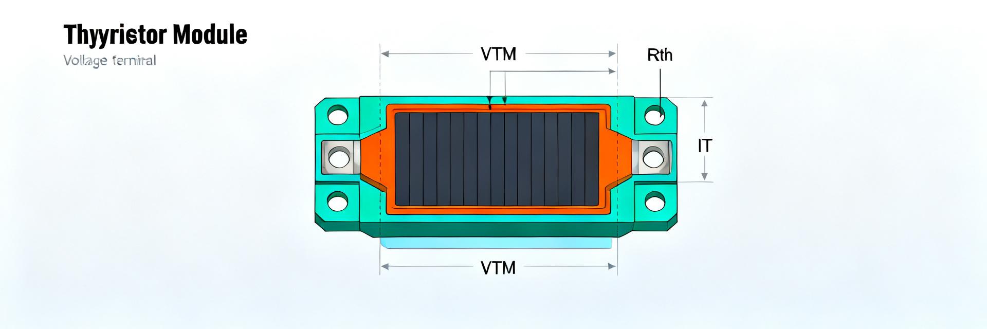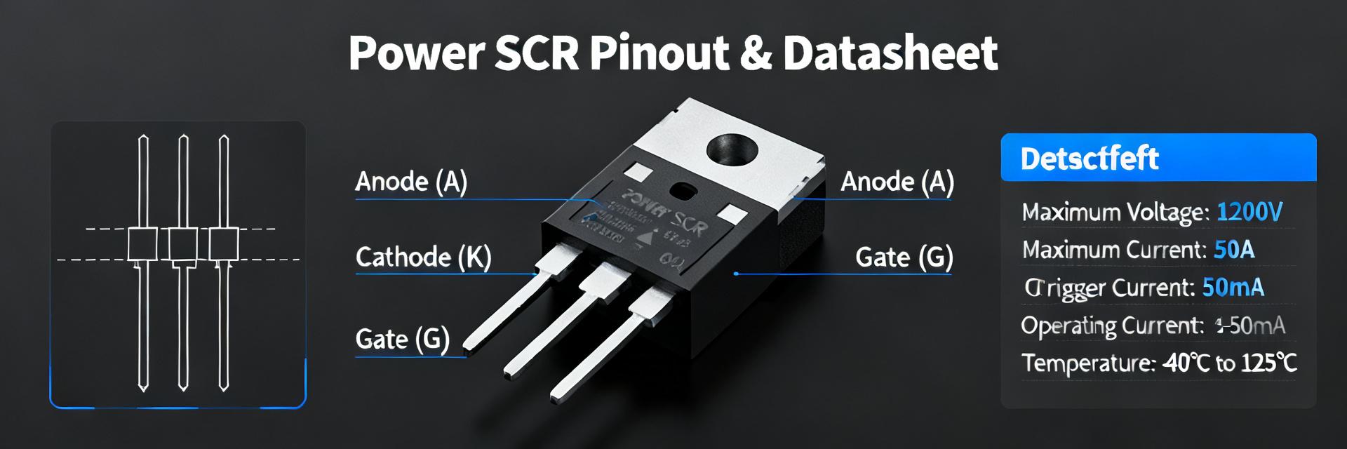
When designers need a heavy-duty SCR with clear electrical ratings and rugged thermal limits, the 03906GRF SCR datasheet is the single reference engineers turn to. Point: this datasheet consolidates key ratings, mechanical outlines and performance curves. Evidence: datasheet tables enumerate voltage, current, surge and thermal parameters. Explanation: using the PDF as the definitive source reduces design iterations and procurement risk.
Content direction: this article explains where the official PDF contents are focused, which electrical, thermal and mechanical items to extract, and who benefits — power engineers, procurement teams, and test labs. Evidence: each section references specific tables and graphs commonly found in SCR PDFs. Explanation: follow the checklist below to move from datasheet review to validated integration.
Part overview & identifiers (background)
Part numbering, package and marking
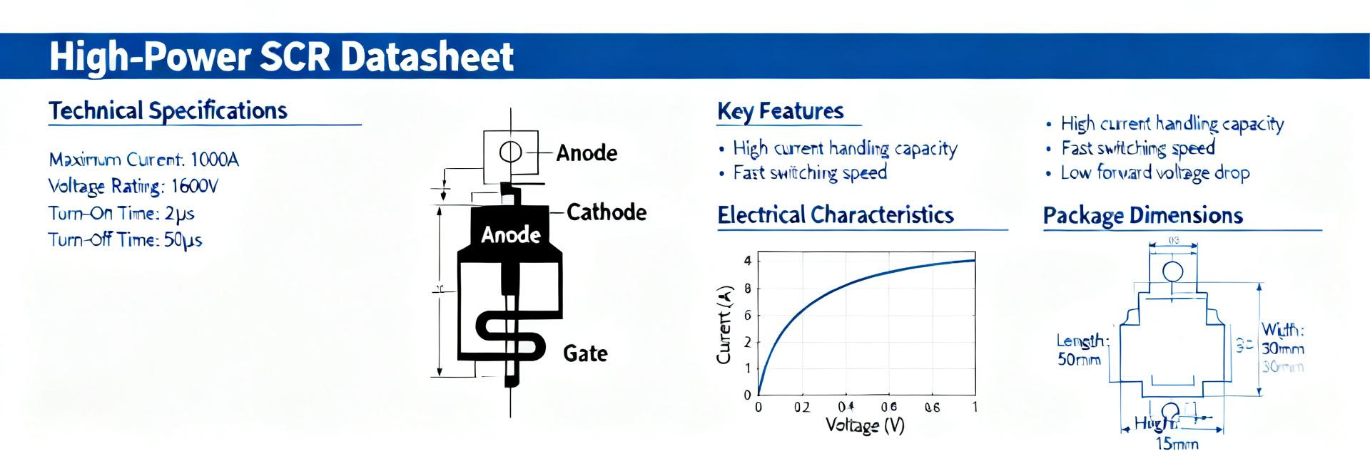
Point: read the part-number suffixes and package outline carefully to match board and heatsink designs. Evidence: the datasheet’s mechanical drawings and marking tables show package outline, pin assignments and typical engraving. Explanation: confirm the suffix for insulated vs. bare case, match the package outline on the board footprint, and verify marking codes during incoming inspection.
Typical industrial roles & target applications
Point: the device is targeted for high-power phase control, rectification and protection in industrial systems. Evidence: datasheet application notes and typical-application diagrams list AC phase-control, controlled rectifiers and motor-drive snubber examples. Explanation: this vendor-neutral guidance helps teams decide whether the part suits industrial drives, welding power supplies or large UPS rectifiers.
Complete industrial specs: electrical ratings & limits (data analysis)
| Parameter | Symbol | Reference Condition | Rating / Range |
|---|---|---|---|
| Repetitive Peak Off-State Voltage | VDRM / VRRM | TJ = -40°C to +125°C | 600V – 1600V |
| RMS On-State Current | IT(RMS) | Conduction angle 180° | Up to 110 A |
| Peak Non-Repetitive Surge Current | IFSM | tp = 10 ms half sine, 50 Hz | 1200 A |
| Critical Rate of Rise of Voltage | dv/dt | VD = 67% VDRM, TJ = 125°C | 1000 V/µs |
| Thermal Resistance (Junction-to-Case) | RθJC | DC operation per junction | 0.28 °C/W |
Voltage and current ratings (steady-state and surge)
Point: identify maximum repetitive and non-repetitive voltages, RMS/average/on-state current limits and IFSM surge ratings. Evidence: the datasheet’s absolute-maximum table and surge-test conditions provide the baseline numbers and test pulse forms. Explanation: design margins depend on correct selection of RMS and surge ratings; always validate IFSM test conditions and duty cycle against your application.
Thermal & mechanical limits
Point: extract RθJC, RθJA, maximum junction temperature and recommended heatsink mounting details. Evidence: thermal-resistance tables and mechanical drawings in the PDF list junction-to-case figures, recommended torque and mounting dimensions. Explanation: use these values to size heatsinks, select insulators and plan thermal verification tests such as junction-to-ambient delta under rated load.
Electrical characteristics & performance curves (data analysis)
On-state, off-state and switching behavior
Point: interpret VTM, leakage currents and blocking characteristics from typical versus maximum curves. Evidence: the datasheet includes static characteristic curves and V-I plots that show typical on-state voltage and reverse leakage across temperature. Explanation: use the 03906GRF SCR datasheet plots to set expected conduction loss, calculate power dissipation and verify driver margins for your switching profile.
Gate characteristics and temperature dependency
Point: review gate trigger current/voltage, holding current, dI/dt and dv/dt ratings plus temperature trends. Evidence: gate-spec tables and temperature-derating curves provide trigger thresholds and safe operating dI/dt envelopes. Explanation: select gate resistors and snubbers based on these numbers and plan qualification tests at elevated junction temperatures to confirm stable triggering.
Application & integration guide (method / how-to)
Recommended gate drive and protection circuits
Point: implement drive resistors, snubbers and transient suppression around the SCR. Evidence: typical-application blocks in the datasheet recommend gate resistor ranges and RC snubber examples along with transient clamp notes. Explanation: start with the recommended resistor and snubber values, then iterate with bench measurements (gate current waveform, dv/dt checks) to finalize component choices.
Thermal design, mounting and PCB best practices
Point: follow recommended mounting torque, heatsink interface and PCB clearance rules. Evidence: mechanical drawings and notes specify mounting hole patterns, insulator thickness options and recommended thermal interface materials. Explanation: verify thermal path with infrared imaging and junction-to-case delta checks during initial commissioning to ensure safe long-term operation.
Field case study: deployment checklist and common failure modes (case example, anonymized)
Example deployment checklist (anonymized)
Point: use a stepwise commissioning checklist to reduce field failures. Evidence: practical checklists derived from datasheet items include incoming marking verification, footprint/mechanical match, basic leakage and gate-trigger tests. Explanation: performing these checks before final assembly prevents mismatch errors and catches counterfeit or incorrect revisions early in the process.
Common issues and troubleshooting steps
Point: typical failures include overheating, improper gate drive and dv/dt turn-on. Evidence: symptom patterns and corrective actions align with datasheet limits — excessive VTM indicating thermal stress, or unintended conduction tied to insufficient gate damping. Explanation: isolate root causes with targeted tests: thermal scans, gate waveform capture and controlled dv/dt injection.
Sourcing, compliance & testing checklist (action/advice)
How to verify datasheet authenticity and PDF items to confirm before purchase
Point: validate the PDF revision, units and test conditions before procurement. Evidence: the datasheet revision block, table units and footnotes list test pulse widths, ambient conditions and mounting assumptions. Explanation: request the official revision identifier, compare mechanical drawings to received parts and search for mismatch in test-condition definitions to avoid wrong-spec purchases for critical runs. Also search long-tail phrases like “03906GRF SCR datasheet PDF download official revision” when validating sources.
Compliance, handling and storage notes for industrial use
Point: treat high-power SCRs with ESD precautions and proper storage; verify compliance claims. Evidence: handling notes in datasheets typically recommend ESD protection, dry-pack storage and temperature limits; compliance declarations are often summary checkboxes. Explanation: treat RoHS/REACH or equivalent statements as procurement checkpoints and confirm packaging moisture-sensitivity level where applicable.
Summary
- Use the 03906GRF SCR datasheet as the authoritative source for electrical and thermal industrial specs, extracting absolute maximums, surge IFSM conditions and thermal resistances before design.
- Confirm package outline, marking and mounting details against board and heatsink mechanical drawings to prevent assembly errors and ensure thermal path integrity.
- Follow datasheet gate, dv/dt and snubber guidance; validate gate resistor choices and perform thermal imaging and junction-to-case delta checks during commissioning.
Frequently Asked Questions
What key datasheet tables should I verify first for 03906GRF selection?
Answer: Start with absolute-maximum ratings, surge test conditions and thermal-resistance tables. Verify repetitive and non-repetitive voltage limits, IFSM pulse width and junction-to-case thermal resistance to ensure the part meets your steady-state and transient demands.
How should I size a snubber and gate resistor for an industrial SCR?
Answer: Use the datasheet’s recommended gate trigger current and dv/dt rating as starting points. Calculate gate resistor to limit peak gate current within specified trigger thresholds, and design an RC snubber to keep dv/dt under the rated limit; validate with oscilloscope capture under representative load pulses.
What procurement checks reduce counterfeit or mismatched SCR deliveries?
Answer: Require the official PDF revision identifier, inspect mechanical marking and package outline, cross-check test-condition footnotes, and perform baseline leakage and trigger tests on sample parts. Add lot-level traceability and certificate checks to the procurement checklist to reduce risk.
What causes false dv/dt triggering and how is it prevented in 03906GRF circuits?
Answer: High rate-of-rise transient voltages across the anode and cathode induce capacitive displacement current into the gate, triggering conduction prematurely. It is mitigated by adding a low-inductance RC snubber across the SCR, placing a gate-to-cathode shunt resistor, and providing clean gate drive pulses.