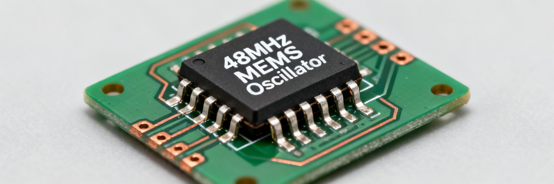
A 40.0000 MHz ultra-compact MEMS oscillator with automotive-grade intent and very low idle current can shrink board area while reducing system power — the DSA6101MA1B-040.0000VAO promises that combination on paper. This deep dive extracts the most relevant details from the manufacturer datasheet and translates them into actionable design guidance for US hardware teams.
| Parameter | Specification Value | Design Impact |
|---|---|---|
| Nominal Frequency | 40.0000 MHz | Main clock for MCU/SoC/Serial link |
| Technology | MEMS (Silicon) | High vibration/shock resistance |
| Grade | Automotive (VAO) | AEC-Q100 qualified reliability |
| Supply Voltage (VDD) | 1.71V to 3.63V | Wide-range battery/LDO compatibility |
| Standby Current | Ultra-Low (Typical < 1µA) | Extends battery life in idle modes |
| Output Logic | LVCMOS | Direct drive for most digital ICs |
Logic & Signal Flow
Background: Product family & intended use
Family overview & typical capabilities
The DSA6101 family targets compact, low-power timing for embedded and automotive applications. The official datasheet lists the product as a MEMS-based oscillator family covering multiple standard frequencies. Designers choose this family when board area, power, and automotive temperature tolerance are priorities.
Typical application domains
The family fits automotive ECUs, telematics modules, and battery-powered sensor nodes. Low standby current preserves battery life in remote modules, while stable frequency across wide temperature ranges supports automotive bus timing and industrial serial links.
Electrical deep-dive — DSA6101MA1B-040.0000VAO key specs
Frequency & stability parameters
Nominal frequency is 40.0000 MHz. Stability options are specified in the datasheet. Budget ppm into PLL lock windows and UART bit error budgets; 1 ppm at 40 MHz equals 40 Hz of deviation, which must be accounted for over the full operating temperature range.
Power, output format & control pins
Supply range, active/standby currents, and enable behavior determine integration. Use the standby current for battery budgeting and ensure MCU I/O levels match the oscillator enable (OE) thresholds. Plan decoupling to handle source-sink transients during startup.
Integration checklist
- BOM Verification: Cross-check the "VAO" suffix for automotive qualification.
- Footprint: Validate against the datasheet land pattern to ensure reliable soldering.
- Signal Integrity: Use a series termination resistor (e.g., 22-33Ω) for long traces.
- Firmware: Implement startup delays to allow frequency stabilization before MCU clock switch.
Frequently Asked Questions
What are the critical datasheet parameters to confirm for DSA6101MA1B-040.0000VAO?
How should I test jitter and phase noise against the datasheet claims?
What production checks map best to the datasheet tolerances?
Why choose MEMS (DSA6101) over traditional quartz for automotive?
Author note: Verify the full orderable code and variant suffixes against the official manufacturer datasheet and package drawing before releasing the BOM; the article title must match the exact orderable code.